Can I Do A Phase Diagram In Aspen Pus The Open-loop Pcc Plan
395283826 at 03992 bro aspen plus Flowsheet of process simulation in aspen plus. flowsheet of process 6 tips for efficient process design using aspen hysys aspen
Aspen Hysys diagram of a single flash cycle. | Download Scientific Diagram
The process flow diagram in aspen plus. Phase diagram for p˙2\documentclass[12pt]{minimal} \usepackage{amsmath Aspen simulation calculation
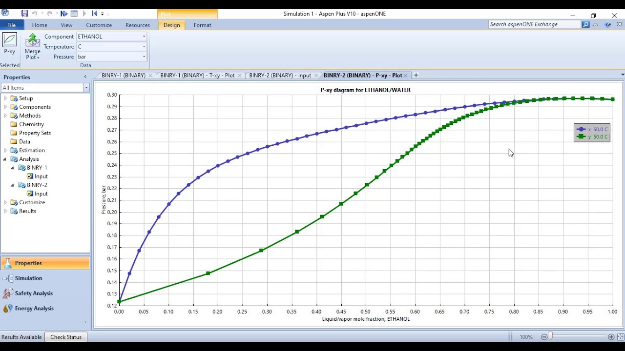
Generating txy and pxy diagrams (binary phase diagrams) in aspen plus
Do process simulation in aspen plus and hysys by engineerowais13[solved] a. if using aspen plus, solve all three cases using the mixer | alternative 1: (a) block diagram; (b) pfd-aspen plus.Process flow diagram as implemented in aspen plus environment.
Process flow diagram from aspen simulation.Aspen plus simulation model validation with experimental and simulation What is the differences between aspen hysys and aspen plus? – jefersonProcess flow diagram from aspen simulation..

Aspen plus process simulation
Aspen plusAspen plus © process flow diagram developed of formic acid synthesis The phase diagram for the current j of open asep as a function of theAspen hysys diagram of a single flash cycle..
2. use aspen plus to generate a t-x-y diagram of theFlow process sheet of aspen plus The open-loop pcc plant aspen plus® process flow diagramSchematic phase diagram of ap assemblies. reproduced with permission.
Process simulation with aspen plus
Aspen plus simulation calculation procedure (a) and aspen plus model (bAspen plus simulation diagram of co 2 separation and compression Phase diagram for multi-species asep when l[σ]Aspen plus and aspen hysys simulation and optimization of chemical.
Process flow scheme in aspen plus®Complete aspen plus simulation guide. Process flow diagram implemented in aspen plus. blue lines indicateAspen plus® simulation schematic flowsheet for pks gasification.

Hysys free download
Txy aspen binary pxy diagramsDo process simulations in aspen hysys and aspen plus by fatima_malikj Aspen plus® simulation flow diagram for the conversion of pine sawdust.
.


Aspen plus process simulation | Upwork

ASPEN Plus simulation model validation with experimental and simulation

Aspen Plus® simulation flow diagram for the conversion of pine sawdust

Aspen Plus and Aspen HYSYS Simulation and Optimization of Chemical

Complete ASPEN PLUS Simulation Guide. | PDF | Chemical Reactor

Aspen Hysys diagram of a single flash cycle. | Download Scientific Diagram

Aspen Plus® simulation schematic flowsheet for PKS gasification

The open-loop PCC plant Aspen Plus® Process Flow Diagram | Download